Product code: AIRMOB-10
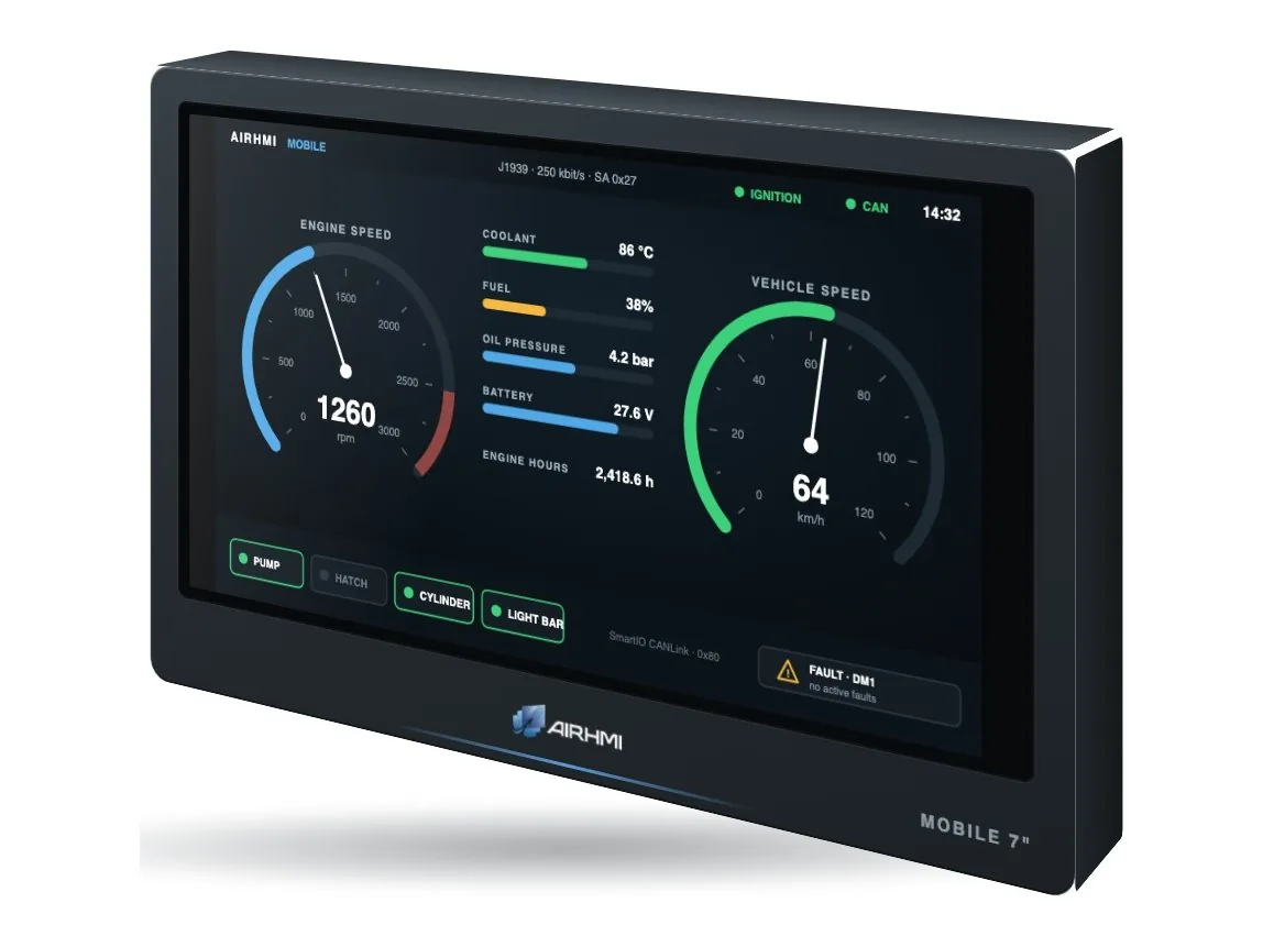
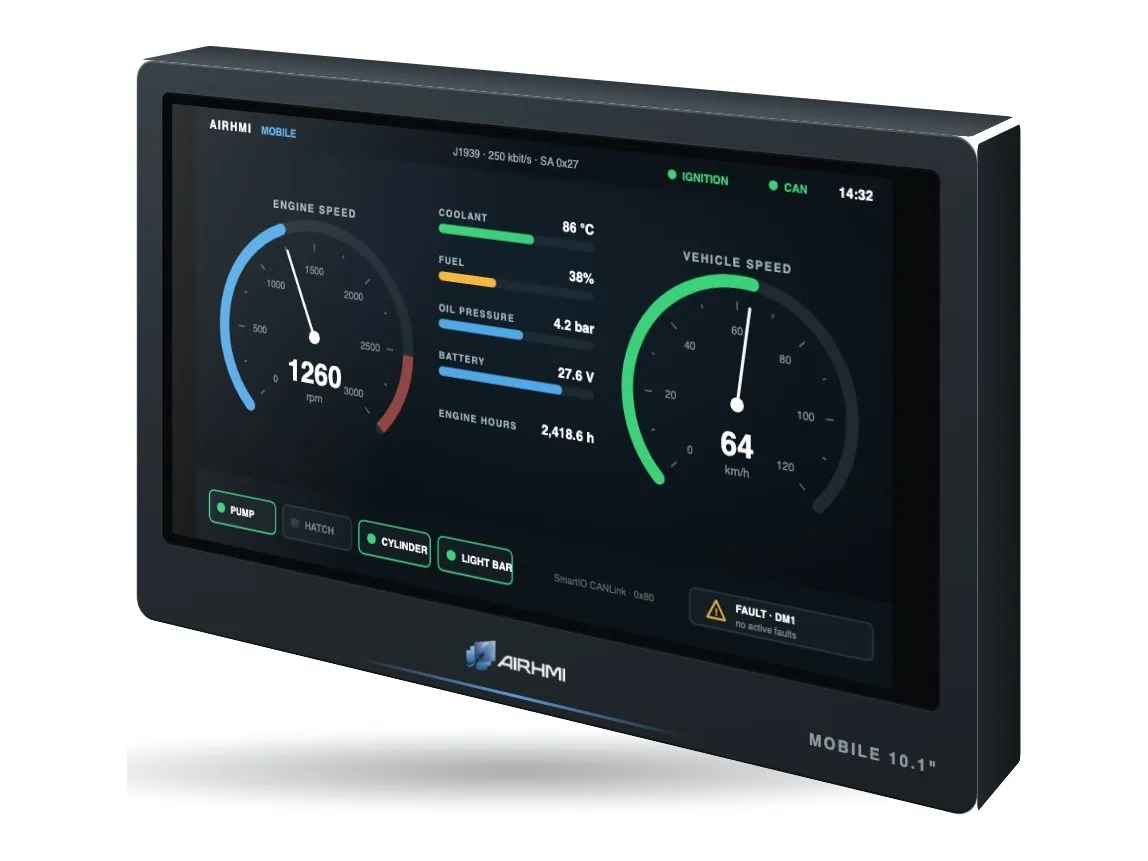
A 10.1" AirHMI Industry display and a CANBus – UART board in one housing. Power, ignition and the CAN bus connect through the 5-pin connector at the back; it reads vehicle data such as engine speed, speed, temperature and fault codes from the J1939 bus and shows it.
AirHMI Mobile is a CANBus HMI display made for construction and agricultural machines, truck and bus bodies and special-purpose vehicles. The AirHMI Industry display and the CANBus – UART board sit in the same housing; from the outside it looks like a single device, with only a 5-pin vehicle connector at the back.
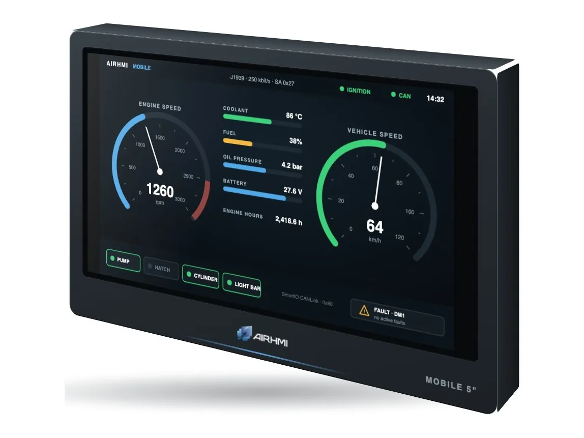
The board filters the 29-bit J1939 messages on the vehicle bus by ID and passes only the ones needed to the display. The project on the display shows data such as engine speed, vehicle speed, coolant temperature, fuel level and DM1 fault codes directly; body equipment such as pumps, valves and lamps is controlled on the same bus with SmartIO CANLink modules.
With a 9–36 VDC supply it runs in 12 V and 24 V vehicles. The ignition (KL15) input senses the vehicle ignition: the display wakes when it is switched on and goes to sleep after a set time when it is switched off, so it does not drain the battery.
The interface is designed by drag and drop in the free AIRHMI Designer; with dial and gauge components and C-based event code you build your own vehicle panel.
The built-in board filters 29-bit J1939 messages by ID
AirHMI Industry: 32 MB flash, video and audio, RTC
Runs directly in 12 V and 24 V vehicles
Wakes when the ignition is on, sleeps after a delay when it is off
5 pins: +24 V, GND, ignition, CAN H, CAN L
Dials, gauges and C-based event code in AIRHMI Designer
Messages broadcast on the J1939 bus are read: engine speed, vehicle speed, coolant temperature, fuel level, oil pressure, battery voltage and DM1 fault codes, for example. The board filters messages by ID and the project on the display decodes and shows them.
It senses the vehicle ignition (KL15): the display wakes when the ignition is on and sleeps after a set time when it is off, so it does not drain the battery while the vehicle is parked.
9–36 VDC; it runs directly in 12 V and 24 V vehicles.
5 pins: 1 +24 V (9–36 VDC), 2 GND, 3 ignition (KL15), 4 CAN H, 5 CAN L.
The interface is designed with the free AIRHMI Designer; if you prefer, our engineering team prepares the project for you.
It is priced by project and quantity; request a quote. In volume projects the interface and housing are adapted to your company.
If you will fit the package to your machines in series, let us prepare pricing by quantity and a delivery plan, and adapt your application together with our engineering team.