Product code: SMARTIO-CAN16
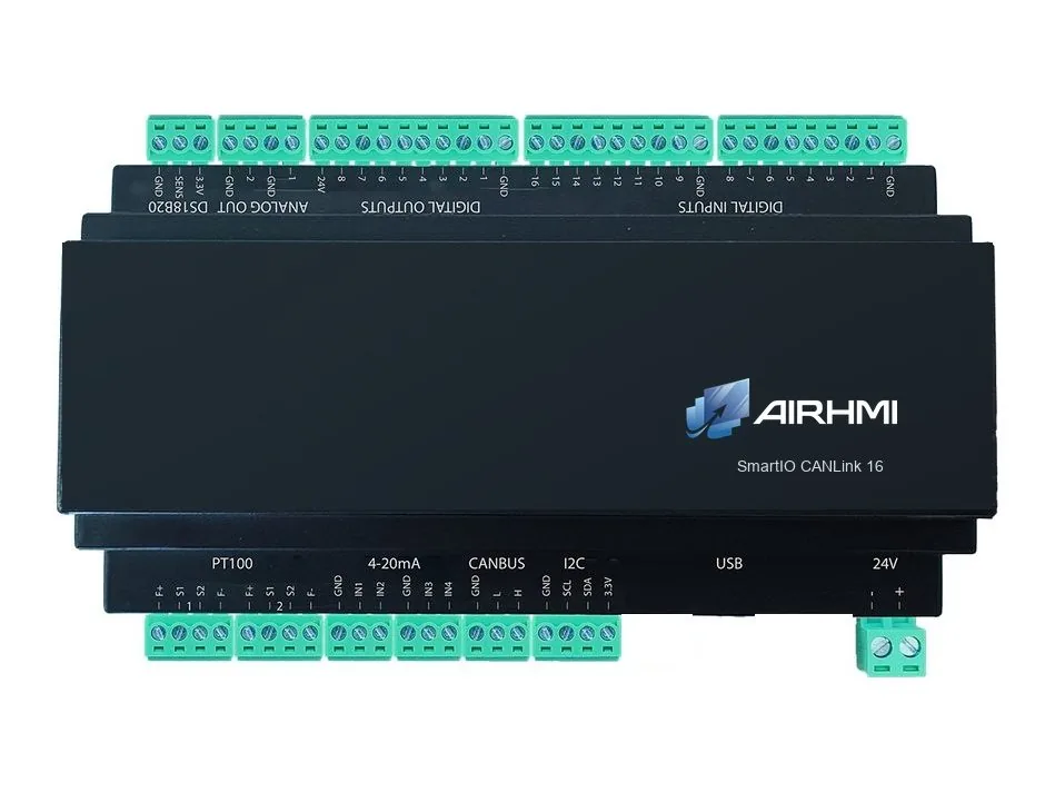
Remote I/O module that connects 16 digital inputs, 8 digital outputs and analog I/O to a single CANBus line. On machines and vehicles, your HMI display, PLC or computer reads and controls the module using CAN IDs you define and SAE J1939.
SmartIO CANLink 16 is a remote I/O module designed to gather field signals over a single CANBus line instead of wiring each one back to the control cabinet. The module runs no program of its own; it sends input states and analog values to CAN IDs you define and receives output commands over CANBus as well.
Digital inputs, digital outputs, analog inputs, analog outputs and temperature inputs each use one CAN ID; in the digital messages every bit is one input or output. CAN IDs are changed over USB with a PC application. Status information is available in two ways: in request–response mode the module only replies when the master asks; in stream mode it sends by itself at the time interval you select. This lets you match the bus load to the application.
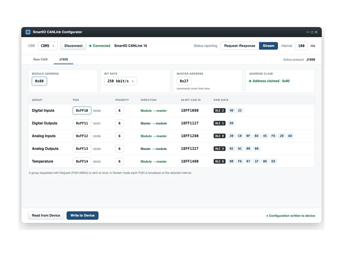
The module works with two protocols. In Raw CAN mode you define the CAN ID of each group. In SAE J1939 mode the module joins the vehicle bus with 29-bit IDs, its own source address and Address Claim; it sends its data with proprietary PGNs and responds to Request messages.
16 digital inputs, 8 digital outputs, 4 × 4-20 mA analog inputs, 2 analog outputs and a DS18B20 temperature input are standard; a 2-channel PT100 temperature input is added as an option when ordering.
With J1939 support and a 9–36 VDC supply, CANLink is also suited to automotive applications: in 12 V and 24 V vehicles, and in buses, trucks, construction machines and special-purpose vehicles it brings cab, body and superstructure signals onto the vehicle bus. Thanks to the noise-immune differential signalling, the module can be placed far from the master, right next to the machine or vehicle; several CANLink modules work on the same bus with different CAN IDs.
J1939 (29-bit ID, Address Claim, PGN) or user-defined CAN IDs
CAN IDs are changed over USB with a PC application; live states, raw data and DLC are shown
States are sent on request or at a selected time interval
9–36 VDC; connects to the J1939 bus of buses, trucks, construction machines and special vehicles
16 digital inputs, 8 digital outputs, 4 × 4-20 mA analog inputs, 2 analog outputs
DS18B20 standard; 2 × PT100 optional
SmartIO CANLink is set up with a PC application connected over USB. In the Raw CAN and J1939 tabs you set the CAN IDs or the J1939 address and PGNs, the reporting mode and the stream interval; inputs, outputs and raw CAN data are monitored live.
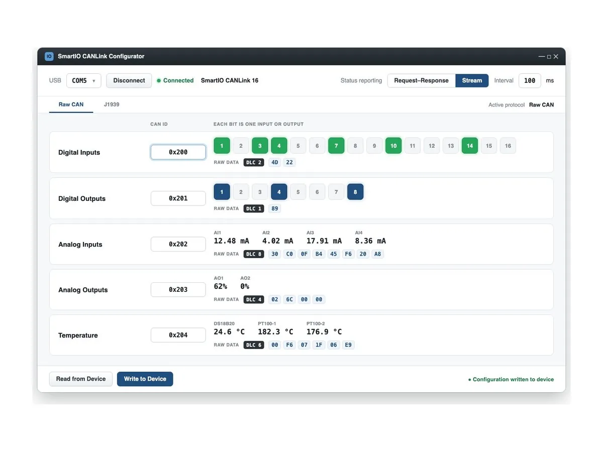
The module only replies when the master asks. With many devices on the bus and data needed only at certain moments, this keeps bus load to a minimum; the master decides when data arrives.
The module sends its states by itself at the interval you choose; the master does not need to send requests. Suited to fast-changing signals, vehicle buses and values that must stay up to date on screen.
Each group uses one message: its own CAN ID in Raw CAN mode and its own PGN in J1939 mode. In the digital messages every bit is one input or output; DLC is the number of bytes in the message.
| Group | Direction | J1939 PGN | DLC | Content |
|---|---|---|---|---|
| Digital inputs | Module → master | 0xFF10 | 2 | Bit 0 = DI1 … bit 15 = DI16; 1 = input active |
| Digital outputs | Master → module | 0xFF11 | 1 | Bit 0 = DO1 … bit 7 = DO8; 1 = output on |
| Analog inputs | Module → master | 0xFF12 | 8 | AI1–AI4, 2 bytes per channel |
| Analog outputs | Master → module | 0xFF13 | 4 | AO1–AO2, 2 bytes per channel |
| Temperature | Module → master | 0xFF14 | 6 | DS18B20, PT100-1, PT100-2; 2 bytes per channel |
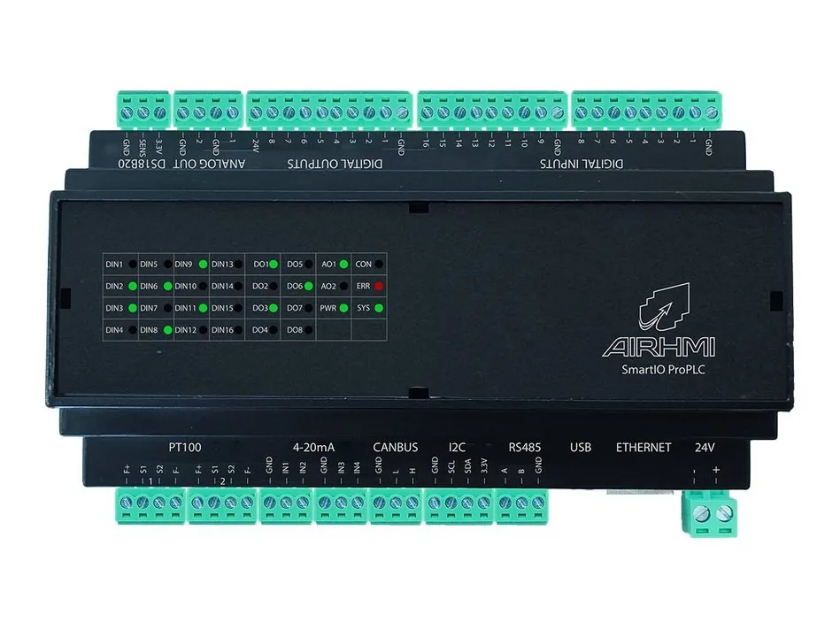
No. SmartIO CANLink is a remote I/O module; the control logic runs on the master device on the CANBus (HMI, PLC or computer). For the Ladder-programmable version, see the SmartIO ProPLC.
Digital inputs, digital outputs, analog inputs, analog outputs and temperature inputs each use one CAN ID; in the digital messages every bit is one input or output. The IDs are changed over USB with a PC application; several modules work on the same bus with different IDs.
Two modes are available: in request–response mode the module only replies when the master asks; in stream mode it sends the states by itself at the time interval you select.
Yes. The module works in Raw CAN or SAE J1939 mode. In J1939 mode it supports 29-bit IDs, a source address, Address Claim, proprietary (Proprietary A / B) PGNs and the Request message; the protocol is selected over USB in the configuration software.
Yes. With its 9–36 VDC supply it runs in 12 V and 24 V vehicles; in J1939 mode it connects to the vehicle bus of buses, trucks, construction machines and special-purpose vehicles to add inputs / outputs.
No. The 2-channel PT100 input is added as a paid option when ordering; the DS18B20 temperature input is standard on both models.
No. Communication is via CANBus. For applications that need Ethernet Modbus and RS485, the SmartIO ProPLC is suitable.
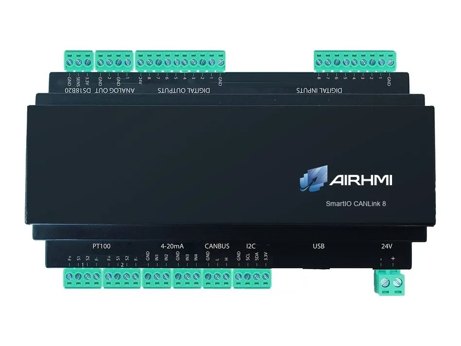
Only the number of digital inputs: CANLink 8 has 8 and CANLink 16 has 16 inputs. Outputs, analog I/O and temperature inputs are identical.
Let's define the right configuration for your project together with our engineering team.